
Key takeaways
-
Surface-mounted lower landing stations and upper landing call-for-assistance buttons can be fixed to railings with clamp brackets to avoid drilling into coping stones.
-
Provide two 32 mm electrical conduits to the lower station and two 100 mm pit entries (stacked vertically) to suit the control cabinet route.
-
Typical call button height range for accessibility is 900–1100 mm from finished floor; 700–900 mm may be considered for seated reach where justified by the applicable standard and project risk assessment.
-
Confirm finish build-ups early; an example shown is 50 mm stone on 15 mm bedding (65 mm total).
-
Agree bracket geometry from a short site rail survey before manufacture; Sesame will adapt clamp profiles for square, round or chamfered posts.
Introduction
This engineering guide details the safe and non-intrusive method for installing a lower landing button station and upper call-for-assistance on existing railings. It is designed for conservation-led and heritage-sensitive projects where preserving original fabric is essential.
What problem does a clamp bracket solve on heritage and sensitive sites?
When conservation officers prohibit drilling into listed stonework, railing-mounted clamp brackets provide a reversible, fabric-safe solution. The approach preserves coping stones, simplifies approvals and delivers a rigid mounting face for controls.
How should the lower landing button station be fixed and wired?
Mount the enclosure on a bespoke clamp bracket fixed to the railing. Provide two 32 mm electrical conduits into the station. If a local draw pit is available, conduits may be run to the pit; otherwise route back to the control cabinet with a good-practice target of 10 m conduit length. Bottom or rear cable entries can be provided; confirm knockout positions at approval. Standard finish is stainless-steel brushed fascia with a powder-coated body; alternative RALs can be matched to the rail.
What height and position should the upper landing call-for-assistance use?
Plan for 900–1100 mm from finished floor level. Where seated reach is the focus, 700–900 mm can be appropriate if it aligns with the project’s chosen standard and is recorded in the design rationale. Size the wrap-around clamp to clear rail stays and accommodate radiused or chamfered corners.
What early information does the design team need to provide?
Confirm finished floor and landing build-ups, identify pit entries at two 100 mm diameters, and share rail drawings or on-site measurements including post width or diameter, corner radii or chamfers, stay positions and available clamping depth. Clarify whether cables return to a local draw pit or directly to the control cabinet.
How do we protect original fabric while keeping the station rigid?
Clamp brackets distribute loads across opposing faces of the rail using non-staining liners. Where rails are slender, a hidden anti-rotation feature and through-strap stabilize the station without drilling into stone or primary structure.
Real-world alternatives and where this is used
Railing-mounted controls are common across Sesame’s bespoke systems, including the Buckingham Listed Building Lift, the Pimlico Lift and the British Library Platform Lift. For projects considering retracting stair solutions outdoors, see the dedicated product family such as Big Ben Electric Stairs.
Traditional fixing vs clamp bracket — what’s the practical difference?
-
Fabric impact: drilling into stone can be non-reversible; clamp brackets are reversible and avoid penetrations.
-
Programme: clamp brackets reduce approval cycles by aligning with conservation goals.
-
Installation: clamp brackets avoid stone drilling time and dust control measures, improving site logistics.
Standards and compliance
Coordinate your design with the project’s chosen accessibility and lifting platform standards. Add an external link to a recognised institute or standards body for your jurisdiction to support approvals and technical referencing (add external standards link here).
Coordination snapshot from design development
Landing finishes updated to a 65 mm total thickness. Two 32 mm conduits are specified to the lower station; two 100 mm pit entries confirmed. The lower station is surface-mounted on a railing clamp rather than fixed to the coping stone. Upper call-for-assistance height range agreed and bracket re-drawn to clear rail stays. Stone to the platform tray confirmed as modular pieces with joints aligned to surrounding grout lines to reduce breakage risk.
Related Knowledge Hub reading
-
Outdoor stair lifts: retracting stairs that reveal a hidden lift
-
Wheelchair lift autonomy: safe controls, clear communication, and user confidence
Suggested image assets and alt text
Select an image via the Asset Manager using the keyword “button station” or “call for assistance” and choose the related drawing.
Alt text example: “Railing-mounted lower landing button station with clamp bracket and twin conduit entries.”
Alt text example: “Upper landing call-for-assistance on handrail with wrap-around clamp.”
Frequently asked questions (FAQ)
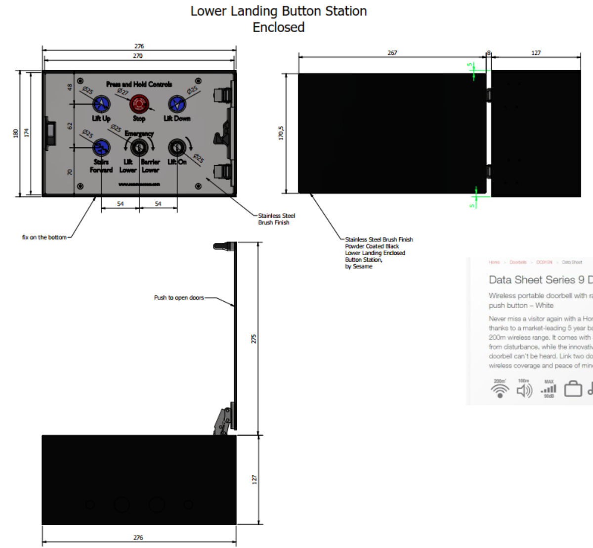
What enclosure size should I allow for the lower landing station?
Allow approximately 270–276 mm width and 170–175 mm height, plus side clearance for a door or hinged cover where used.
Can the station be flush-mounted?
Flush mounting is possible where there is a suitable wall or post. For heritage rails, surface mounting on a clamp bracket is preferred to preserve original fabric.
What load does the clamp bracket distribute and what torque settings are typical?
Design brackets to distribute clamping forces evenly across the rail faces. As a guide, fastener torque is typically set in the range of 6–10 N·m for M6 hardware with lined interfaces, but confirm project-specific values during approval to suit rail material and liner coefficients.
What cable run length should I design for?
A 10 m conduit route to the control cabinet is a practical target; longer runs are possible but need confirmation for voltage drop and serviceability.
Do I need rubber buffers on the enclosure?
Buffers are optional and specified case by case to protect finishes where lids or doors meet the body.
Can the call-for-assistance be set below 900 mm?
Yes, a lower height like 700–900 mm can improve seated reach if it aligns with the chosen standard and is agreed in the project access strategy.
Call to action
Book a 20-minute Teams session with a Sesame Project Manager to review your rail survey, bracket geometry and conduit strategy: https://www.sesameaccess.com/book-a-meeting