
Key Takeaways
-
A lift pit pump system should be designed as part of the lift, not left as a generic building drainage item.
-
Probe levels must be engineered around the lift components you are protecting, not guessed on site.
-
For intermittent ingress and air risk in pipework, an auto-priming pump can be the most reliable choice.
-
A high level alarm with BMS contacts is best practice for commercial sites and helps prevent silent failures.
-
This guidance reflects what Sesame used on a real installation and what we expect to see in builder’s works.
Introduction
Water in a lift pit is common. The difference between a nuisance and a shutdown is whether the pit has a purpose-designed drainage strategy.
This article focuses on lift pit sump pump best practice for platform lifts, including probe configuration, pump selection and alarms. It complements our deeper pit-water planning guides, including Lift pit drainage best practices and Lift pit drainage best practices (Part 2), and adds the engineering decision narrative behind a real-world specification.
Examples of Sesame lifts where pit drainage is routinely engineered into the overall design include the Wellington Lift, Cavendish Platform Lift and fully Bespoke Lift solutions.
Problem: Water builds up in the lift pit
Solution: A defined sump, controlled pump start level, and alarmed discharge
A reliable lift pit pump system has three jobs.
It removes water consistently.
It starts early enough to protect the lift.
It escalates when something is wrong.
What we specified on a real Sesame installation
We specified a dedicated lift shaft pump station with a sealed enclosure and a controlled level system. The core specification included an IP66 steel enclosure, an auto-priming stainless steel pump, a simplex controller, and multi-level floats with BMS outputs.
Key parameters that matter in design reviews:
Manometric suction lift capability up to 9m.
Maximum discharge lift up to 55m.
BMS dry contacts available for integration.
Three float switches with 5m leads for level logic.
These are not marketing numbers. They define whether a system will cope with real discharge heights and whether it can be monitored.
Why we specified this, not that
Many contractors default to a submersible pump because it is common in sumps.
Lift pits are different.
Lift pits often see intermittent ingress, sediment, and long idle periods. Air can enter suction lines and prime can be lost depending on layout and stop-start behaviour.
On this install, we specified an auto-priming stainless steel pump because the duty profile and air-ingress risk demanded a system that can recover reliably after downtime.
This is the same type of engineering thinking we apply when we integrate drainage into constrained architectural entrances, where access, aesthetics and reliability all matter.
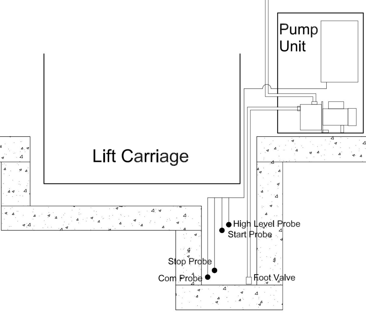
What the cross-section image should show and how to read it
Your lift pit pump cross-section is a simple way to communicate system intent to builders and M&E teams.
It should clearly show:
A defined sump or low point.
A foot valve/strainer positioned just above the pit floor.
A common reference probe at the lowest point.
A start probe.
A stop probe.
A high level alarm probe.
The cross-section you provided is consistent with that logic and helps prevent one of the most common issues: probe placement that is too high or too low for the lift hardware being protected.
Installation details that prevent 80% of failures
The following installation points are small details that make a big difference in reliability.
The enclosure must be mounted using fixings suitable for the wall construction and the unit weight.
A single phase supply is typical, with a fused spur recommended.
The power supply should terminate into the rotary isolator in the pump controller.
Earth bonding should be applied to the enclosure and copper pipework.
For suction, 28mm copper is commonly used, with a strainer foot valve fitted at the bottom.
The foot valve should be positioned 5–10mm above the pit floor to avoid drawing in debris while still evacuating as low as practical.
These are the kind of details that separate an engineered pump system from a generic pump dropped into a void.
Probe and float configuration best practice
A controlled probe layout is what turns a pump into a system.
The logic is:
Common probe at the bottom of the pit.
Start probe at the level where water must not rise further.
Stop probe set to prevent short-cycling while still lowering the water line.
High level probe used only for alarm and escalation.
A short quote that captures the design intent is:
The next probe turns the pump on at the point you do not want the water to rise any further.
A second quote that matters in handover is:
We test each unit before it leaves our works.
A third quote that saves site time is:
The top probe is the alarm.
Suitability matrix: when this approach is right and when it isn’t
Use this approach when:
Suction lift requirement is within the system capability.
Discharge head is within the system capability.
The site is single phase and needs a compact wall-mounted pump station.
Water ingress is intermittent or moderate and reliability after idle periods matters.
You need BMS outputs or a beacon/sounder interface for escalation.
Consider alternatives when:
The pit is deep or has frequent high inflow and you need duplex duty/standby resilience.
The discharge arrangement requires special compliance or treatment.
There is a credible risk of oil contamination entering the discharge line, in which case an oil separator may be required depending on discharge point and local rules.
Common misconceptions and common design failures
Misconception: a submersible pump is always the best option for a lift pit.
Correction: submersible is not automatically best. Lift pits often have intermittent duty and air/prime considerations depending on layout. Engineering selection should follow duty profile and access constraints.
Misconception: the pump start level does not matter as long as the pit drains eventually.
Correction: start level must be engineered to protect the lift components. It should be set below sensitive equipment and interfaces, not chosen at random.
Misconception: any float switch arrangement will work.
Correction: a structured common, start, stop and alarm configuration reduces false triggers and provides a clear escalation path.
Misconception: pit drainage is purely a builder’s works item.
Correction: pit drainage affects lift uptime. It should be part of the coordination scope early, alongside pit waterproofing strategy and penetrations. See Lift pit drainage best practices and Lift pit drainage best practices (Part 2).
Product integration summary
Lift pit drainage design applies across many Sesame platforms, but pit geometry and risk profile vary. These links are examples where drainage and pit detailing are regularly engineered into the overall solution:
Comparison snapshot:
| Scenario | Typical pit water profile | Recommended drainage approach |
|---|---|---|
| Intermittent ingress, long idle periods | Short bursts after rain or cleaning | Auto-priming pump station, structured probes, high level alarm |
| Higher inflow, continuous seepage | Water rises frequently | Duty/standby strategy, increased capacity, consider duplex arrangements |
| Discharge to public system with contamination risk | Possible oil contamination | Add treatment measures such as separators where required |
Frequently Asked Questions
What is lift pit sump pump best practice?
Best practice is a defined sump, correct pipe sizing, engineered probe levels, and a high level alarm with monitoring. The goal is predictable water control and predictable escalation.
What pump specification matters most for a lift pit?
Suction lift, discharge head and controller/alarm integration are key. On our real install, the selected station supported up to 9m suction lift and up to 55m discharge lift with BMS contacts.
How high should the pump start probe be set?
Set it at the point you do not want water to rise beyond, based on the lift pit components and interfaces.
Do I need a high level alarm in the pit?
Yes for most commercial sites. A high level alarm is the difference between early intervention and discovering the issue after a shutdown. BMS contacts and optional siren/beacon outputs support escalation.
Can I just run a discharge into the nearest drain?
Sometimes, but if discharge is to a water course or public drains and there is potential oil contamination, a separator is usually required.
What pipe size should be used for lift pit pump systems?
28mm copper is a common engineered choice for suction and discharge runs in this type of system.
Long-tail query: what causes lift pit pumps to fail?
Common causes include poor probe placement, foot valve sitting in debris, lack of alarm integration, and incorrect pump selection for head and duty profile. A 5–10mm foot valve clearance and tested probe wiring reduce failure risk.
Long-tail query: what is a lift shaft pump station and why use one?
A lift shaft pump station is a packaged enclosure with pump, controller, pipework and alarm contacts designed for lift pits. It simplifies commissioning and improves reliability versus ad-hoc assemblies.
Next step
If you want your builder’s works and M&E scope to align with a reliable lift pit drainage design from the start, book a Teams Meeting with a Sesame Project Manager using this link: