
Key Takeaways
Phase 4 focuses on analysing the first physical version of the Traversing Lift to extract real-world engineering lessons and apply them to the new generation.
The original prototype proved that stability, safety and visual discretion could coexist, but it also revealed where installation, servicing and component packaging could be improved.
These findings are now being used to make the new design shorter, easier to install, easier to maintain and more adaptable to constrained buildings.
What is a Traversing Lift?
A traversing lift is a wheelchair platform lift that moves both vertically and horizontally, allowing a user to travel across voids, staircases or architectural barriers where a conventional vertical lift or stairlift cannot be installed.
Unlike stair-based systems such as the Mayfair Stairlift or Regent Wheelchair Platform Stairlift, a traversing lift provides a level, flat platform that glides across space before rising, creating step-free access without visually dominating the building.
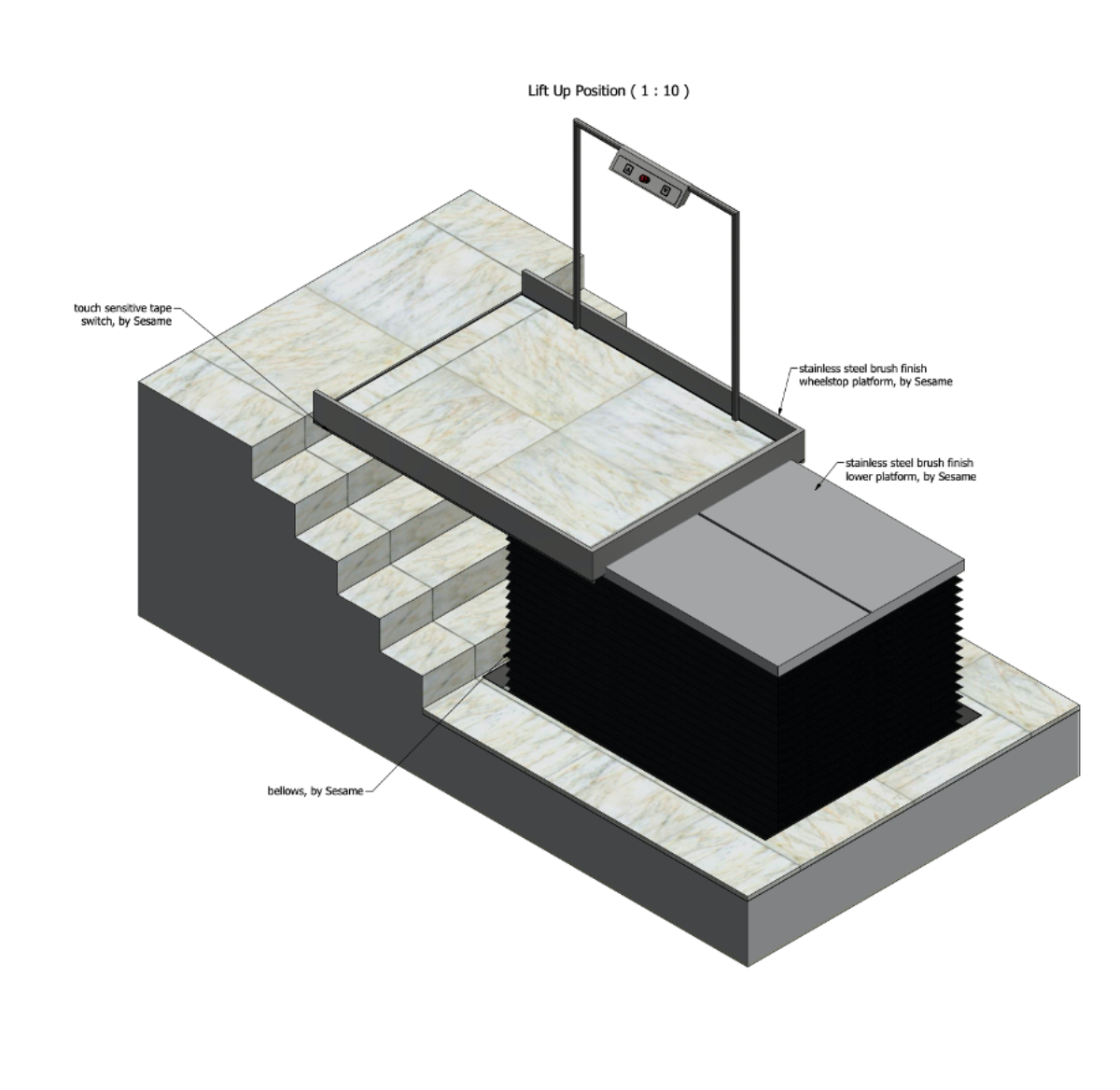
What is a Tape Switch Assembly?
A tape switch assembly is a pressure-sensitive safety edge that stops the lift if any obstruction is touched. It is used to protect all moving edges and gaps so there are no exposed crush hazards.
In the Phase 4 design, the tape switch assembly is now mounted on a removable plate rather than being fitted directly into structural extrusions. This means safety components can be replaced off-site and bolted back into place quickly, improving long-term reliability and serviceability.
Original Prototype vs Phase 4 Design
| Feature | Original Prototype | Phase 4 Design |
|---|---|---|
| Platform length | Approximately 1810 mm | Approximately 1760 mm |
| Platform length reduction | Baseline | Around 50 mm shorter |
| Pit integration | Multiple loose trims and brackets | Integrated dismountable pit frame |
| Bellows mounting | Angled brackets and offset fixings | Box-section mounted and self-supporting |
| Tape switch replacement | On-site extrusion removal | Off-site plate swap |
| Installation time | High due to on-site fitting | Reduced through factory-built assembly |
| Maintenance access | Restricted | Open and modular |
Introduction
Phase 4 follows directly from the development journey documented in Phase 1, Phase 2 and Phase 3.
Phase 1 established why a true hidden traversing lift was needed
https://www.sesameaccess.com/knowledge-hub/traversing-lift-development-phase-1
Phase 2 introduced the single-scissor modular architecture
https://www.sesameaccess.com/knowledge-hub/traversing-lift-development-phase-2
Phase 3 refined safety edges, bellows and geometry
https://www.sesameaccess.com/knowledge-hub/traversing-lift-development-phase-3
Phase 4 is where real engineering happens. The original low-profile traversing lift that Sesame Access physically built was examined in detail, allowing the team to identify which solutions worked and which added unnecessary complexity.
Those lessons are now being transferred into the new scissor-based Traversing Lift.
Solving Space Constraints with Shorter Platform Geometry
The original prototype prioritised ultra-shallow pit depth, which forced components to be stacked in complex ways. By allowing a deeper pit in the new design, Phase 4 was able to reposition actuators, channels and bellows.
This reduced the platform length by around 50 mm without reducing usable travel, making the lift easier to fit into tight architectural footprints similar to those served by the Pimlico Lift and Marylebone Access Lift.
Eliminating Crush Hazards with Box-Section Bellows Mounting
The bellows protect the moving platform and prevent users from reaching moving components. On the original lift, the bellows required multiple brackets that consumed space and created awkward tolerances.
In Phase 4, the bellows are mounted directly to welded box sections inside the frame. This keeps the bellows perfectly aligned with the tape switches and ensures they never collapse into the safety edges.
This approach mirrors the clean protective detailing found in lifts such as the Windsor Lift and Buckingham Listed Building Lift.
Making Safety Systems Simpler and More Reliable
The new removable tape switch plates eliminate the need for on-site fitting of rubber safety edges. Each plate can be removed, serviced or replaced as a complete unit.
This dramatically improves long-term reliability and reduces service visits, which is especially important in high-traffic buildings where systems such as the Westminster Equality Act Lift and Cambridge Part M Lift are typically installed.
Ease of Maintenance and Servicing
The Phase 4 design introduces several service-first improvements:
-
Removable tape switch plates allow off-site replacement
-
Dismountable pit frame enables full lift removal without demolition
-
Bellows mounting is self-supporting and needs no realignment
-
Hydraulic rams are now mounted with welded slotted plates for fast replacement
These upgrades make the system suitable for heritage, commercial and public buildings where downtime must be minimised, similar to applications using the Wellington Lift and Waterloo Lift.
Technical Specifications
Vertical and Horizontal Movement
-
Vertical rise of approximately 1000 mm
-
Horizontal traversing distance designed to suit stair voids and architectural openings
Platform
-
Usable travel length approximately 1745 mm
-
Overall platform length approximately 1760 mm
-
Designed to maintain Part M compliant usable width
Structure
-
Single scissor lift base
-
Modular traversing frame
-
Integrated box-section bellows mounting
Power and Control
-
Hydraulic vertical lift system
-
Linear actuators for horizontal traverse
-
Pressure-sensitive tape switch safety edges
Compliance
-
Designed to meet BS 6440 platform lift safety requirements
-
Suitable for Equality Act and Part M compliance
-
No exposed crush hazards
Frequently Asked Questions
What pit depth does a traversing lift require?
The Phase 4 design uses a deeper pit than the original prototype, allowing simpler engineering and shorter platform length. Typical pit depths are in the region of 500 to 600 mm depending on configuration.
How does a traversing lift comply with BS 6440?
The system uses pressure-sensitive tape switch assemblies on all moving edges and incorporates bellows to eliminate pinch points, meeting the safety requirements of BS 6440.
What is the load capacity of a traversing lift?
The system is designed for wheelchair users and powered mobility devices, with capacities typically in the 300 to 400 kg range depending on specification.
How wide is the usable platform?
The lift is designed to provide at least 800 mm of usable width to comply with Part M and Equality Act requirements.
Can the traversing lift be used in listed buildings?
Yes. The hidden design and minimal visible structure make it suitable for sensitive environments similar to installations of the Edinburgh Access Lift and Kensington Stairlift.
How is the lift serviced?
Tape switches, bellows and actuators are all modular and can be replaced without dismantling the pit or surrounding finishes.
What happens if a safety edge is triggered?
The tape switch assembly immediately stops movement, preventing any crushing or trapping.
Can the lift be removed in the future?
Yes. The dismountable pit frame allows the entire unit to be lifted out if the building is altered.
How does this compare to a standard platform lift?
A traversing lift crosses open space and stairs, whereas a conventional platform lift only moves vertically.
Next Step
If you are designing or upgrading an accessible route through a challenging building, the new generation of the Traversing Lift offers a discreet and technically advanced solution.
Book a Teams meeting with a Sesame Access Project Manager here
https://www.sesameaccess.com/book-a-meeting